Preparation of the Experiment
Over time, I have built several digital clocks controlled by the DCF77 timecode transmitter near Frankfurt/Germany. I have tested different DCF77 reception modules and ended up with the DCF77 Atomic Clock Receiver V4 77.5kHz for Europe by the Canadian company CANADUINO. This module provided stable reception quality and good documentation.
The DCF77 reception modules use a ferrite antenna. Such antennas have a directional characteristic, i.e. for best reception it should be pointed orthogonally relative to the transmitter, see the CANADUINO Datasheet.
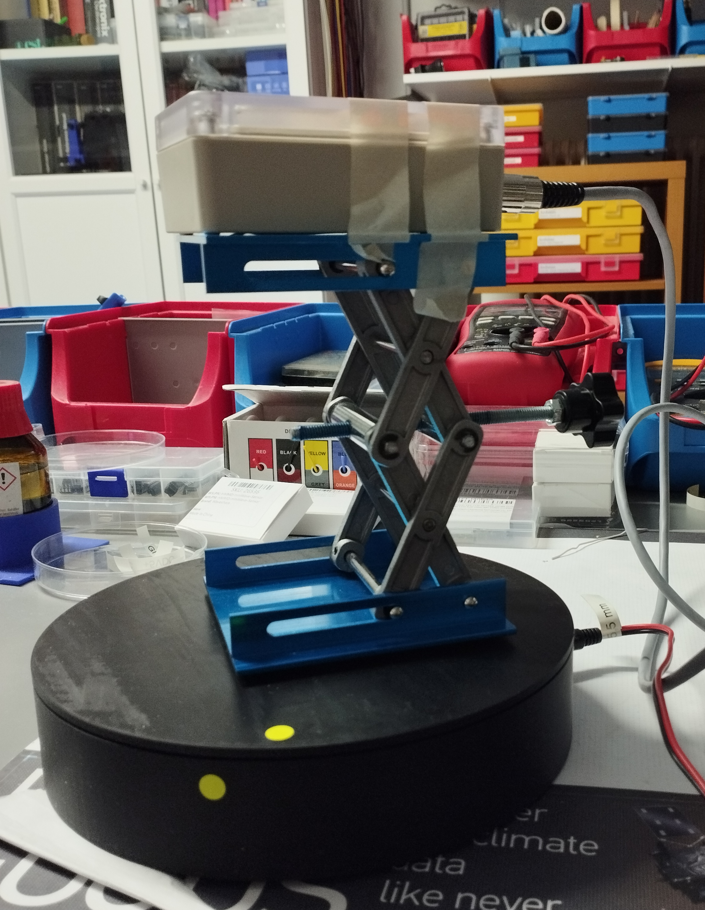
Now I have a Rotating Turntable, modified such that it can be controlled remotely via WiFi. This allows rotating the DCF77 reception module to any angle position relative to the DCF77 transmitter.
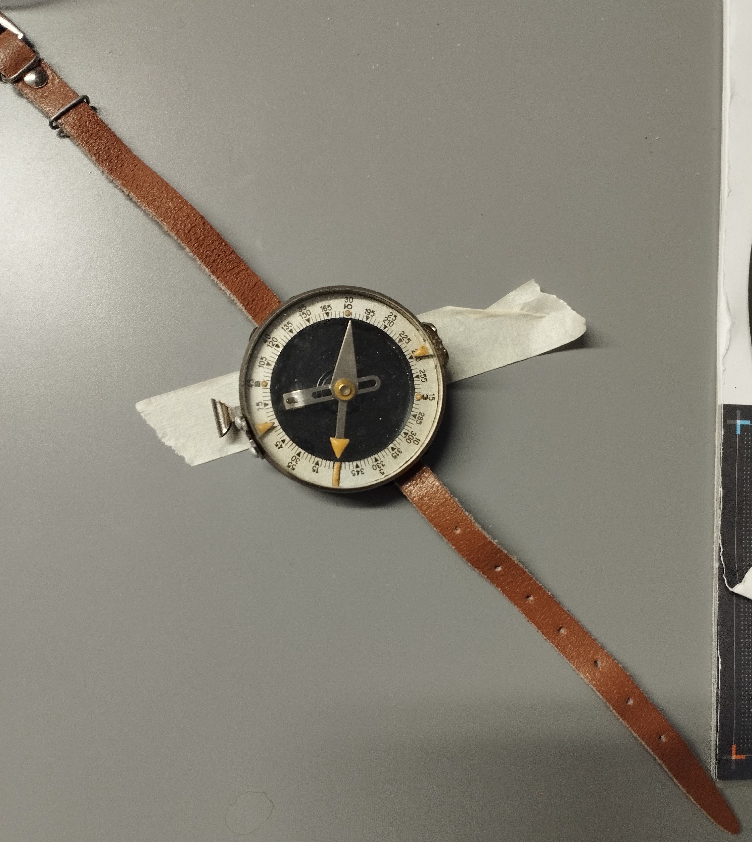
Google provided me with the absolute direction from my home to the DCF77 transmitter. The DCF77 transmitter is at only 50 km distance from my home, so that I can expect stable reception via ground-wave during day or night. With the help of a old-fashioned compass (Made in USSR) I oriented the turntable and DCF77 reception module so that the best reception should be at zero angle.
Custom Software
I have programmed a custom software for the measurement that does the following:
- Initialise all equipment
- Position the turntable at -90 degrees (equivalent to 270 degrees)
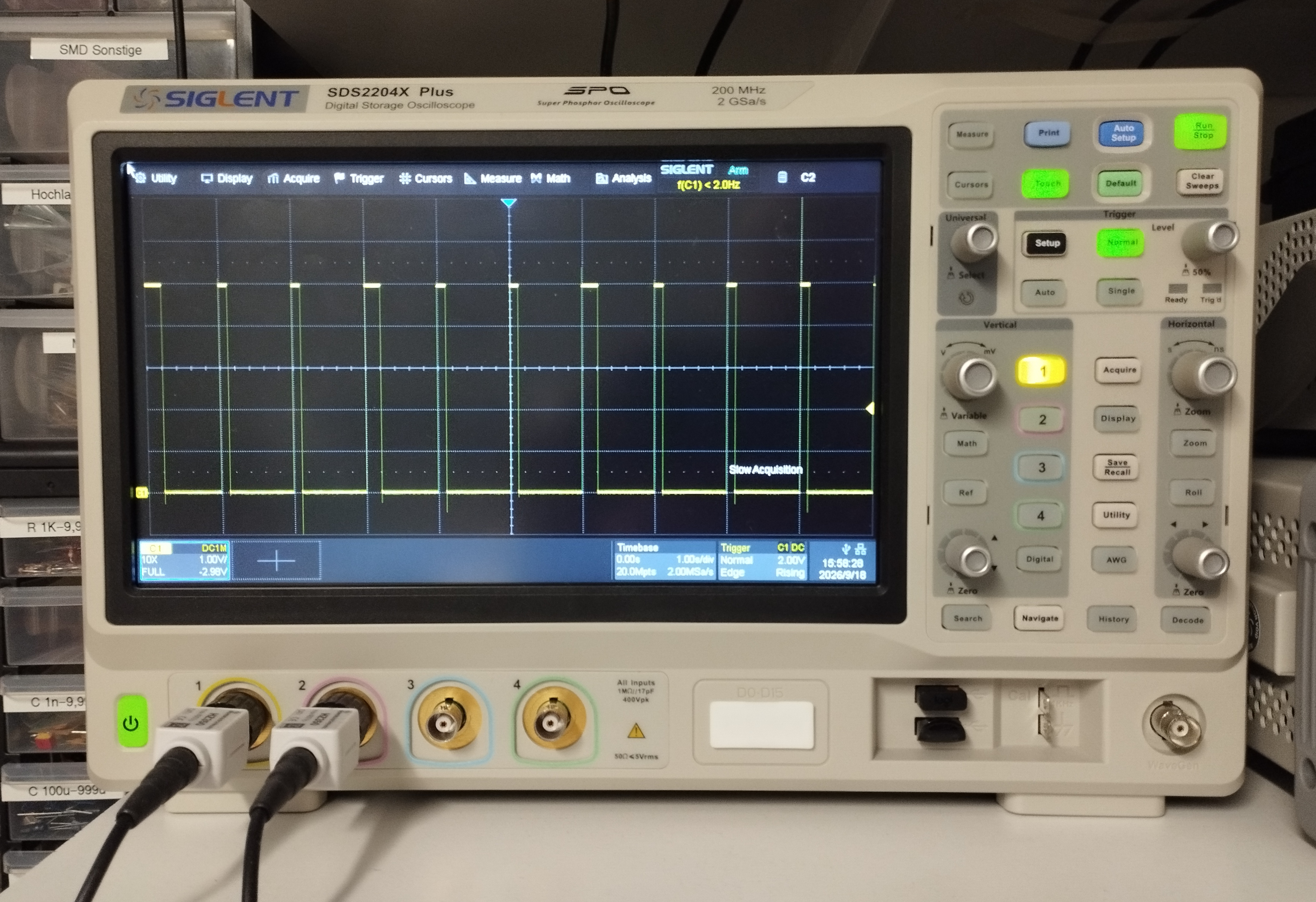
- Observe the output pulses of the DCF77 reception module for a full minute
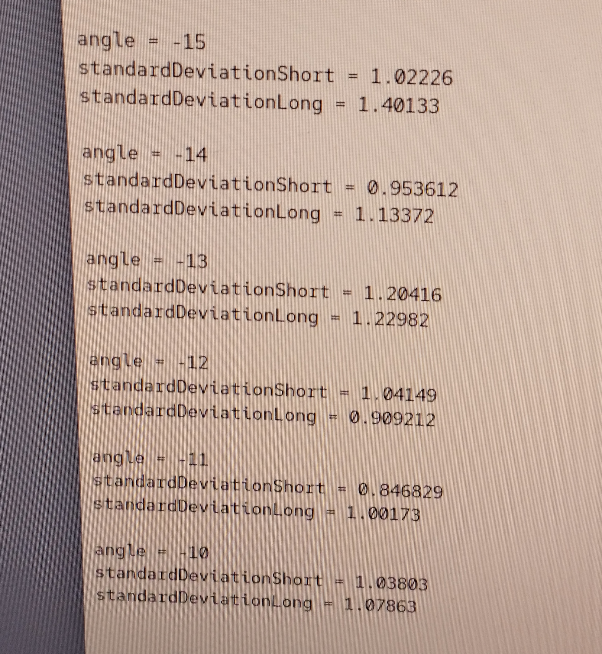
- After detecting between short (100ms) and long (200ms) pulses, determine the standard deviation for duration of the pulses
- Output into a CSV file the angle position, standard deviation for short pulse / long pulse / pulse interval
- Move the turntable by 1 degree and repeat the measurement, finishing when position +90 degrees has been reached
Measurement Results
With the help of the gnuplot software, the measured values recorded in the CSV file can be converted to a diagram. The diagram uses polar coordinates to show the standard deviation versus the antenna angle of the DCF77 reception module.
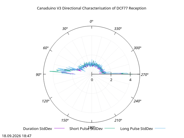
The diagram shows the best reception (i.e. low standard deviation) over a broad range between -75 (285) and +75 degrees. The reception becomes really bad (i.e. high standard deviation) at the angle extremes near +/- 90 degrees.
The distance from my home to the DCF77 timecode transmitter is only 50 km, so the radio signal is rather strong. In case of greater distances the radio signal will be weaker and I would expect the best reception would occur only over a narrower range, e.g. between -45 to 45 degrees.
In case of radio signal interference by other devices (e.g. switched mode power supplies), the best strategy can be to orient the antenna not for the maximum DCF77 signal but for the minimum signal from the interfering device.
Some Notes regarding the Experiment
For the directivity of the ferrite antenna you would normally measure and record the received signal amplitude. However, this value cannot be accessed easily from the DCF77 reception module as it is high-impedance and has very small amplitude. For the actual use in a digital clock, however, the standard deviation of the output pulses can be considered a good indicator of the reception quality of the time signal.
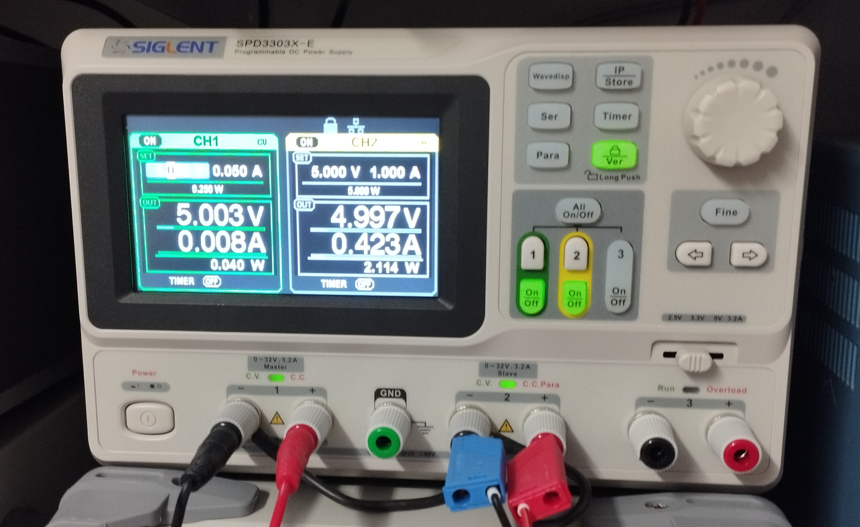
During the first round of measurements, I got no useable pulses. The DCF77 reception module did not lock. It turned out that the switch-mode power supply used for the turntable produced signal interference at the 77.5 kHz radio frequency used for the time code signals. After changing to a linear power supply, the reception returned to normal.
I have used a "tower" to mount the DCF77 reception module high above the turntable, in order to avoid any possible radio interference from the ESP32-based Arduino module and stepper motor.
The measured standard deviation is ca. 1 ms for the best case orientation. Since the pulse detector uses the Arduino "millis()" command to measure pulse duration and pulse interval, there is always some rounding involved and no better results can be expected even if the DCF77 reception module might be producing more accurate pulses.
The experiment and measurements have been executed using an earlier V3 version of the DCF77 reception module from CANADUINO. I understand the main difference between V3 (with voltage regulator) and V4 (without voltage regulator) is the supply voltage handling. I do not expect any relevant difference in reception quality between the V3 (older) and V4 (current) modules.
You can find further interesting details about different DCF77 reception modules at Wolles Elektronikkiste - Die wunderbare Welt der Elektronik.
Photographs of the Experiment
Experiment Setup with Turntable
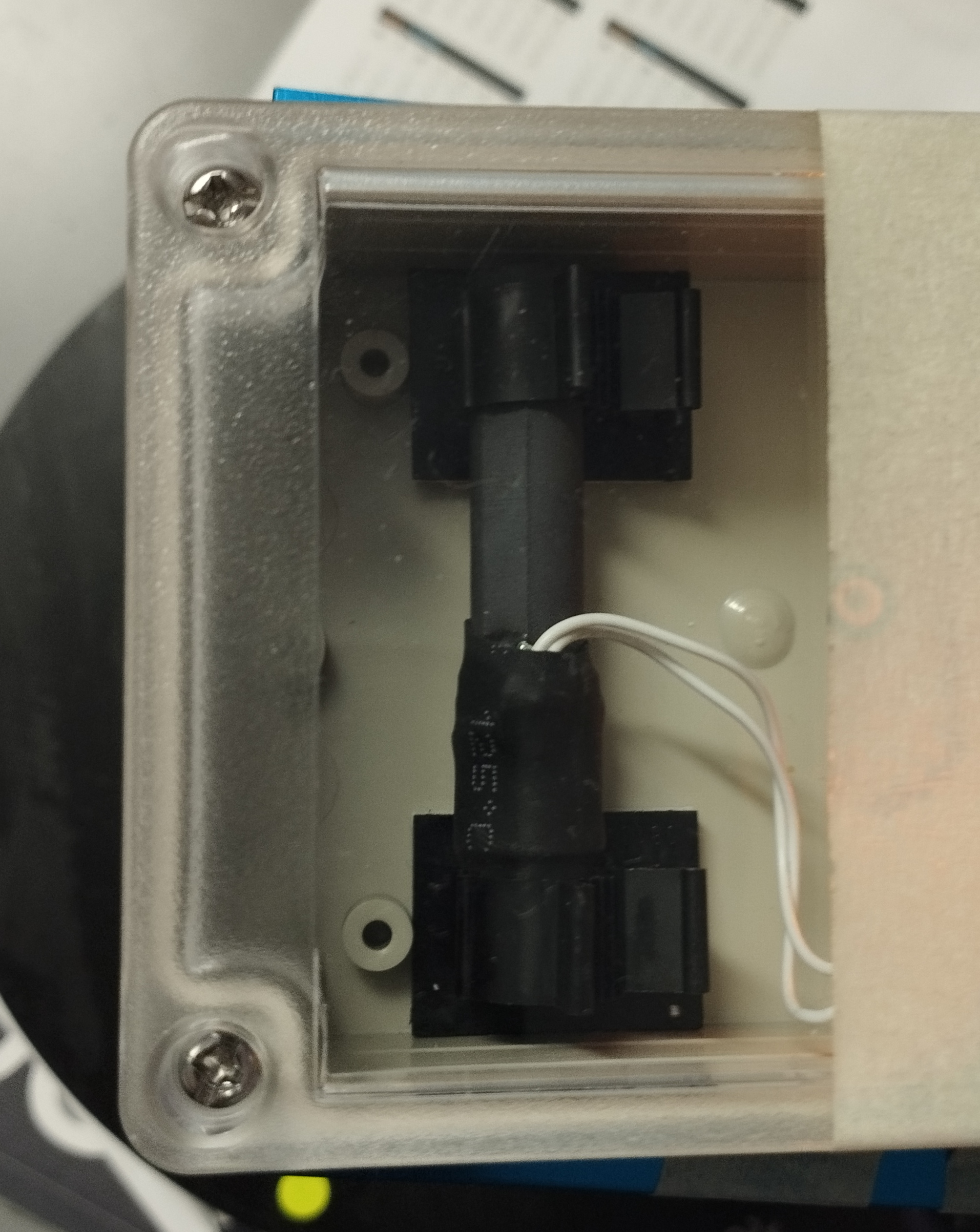
DCF77 Reception Module
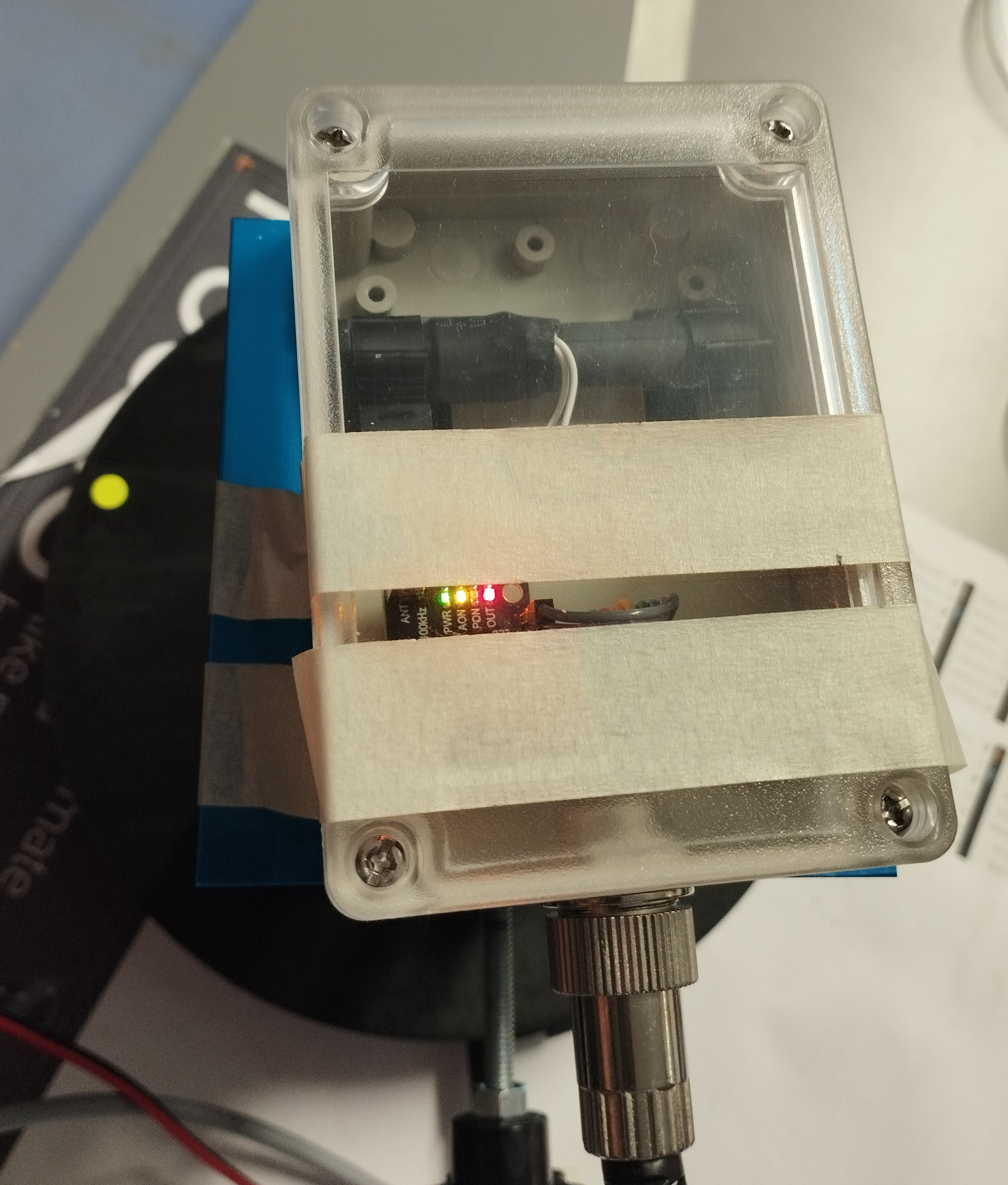
Ferrite Antenna
Compass (Made in USSR)
Pulses on Oscilloscope
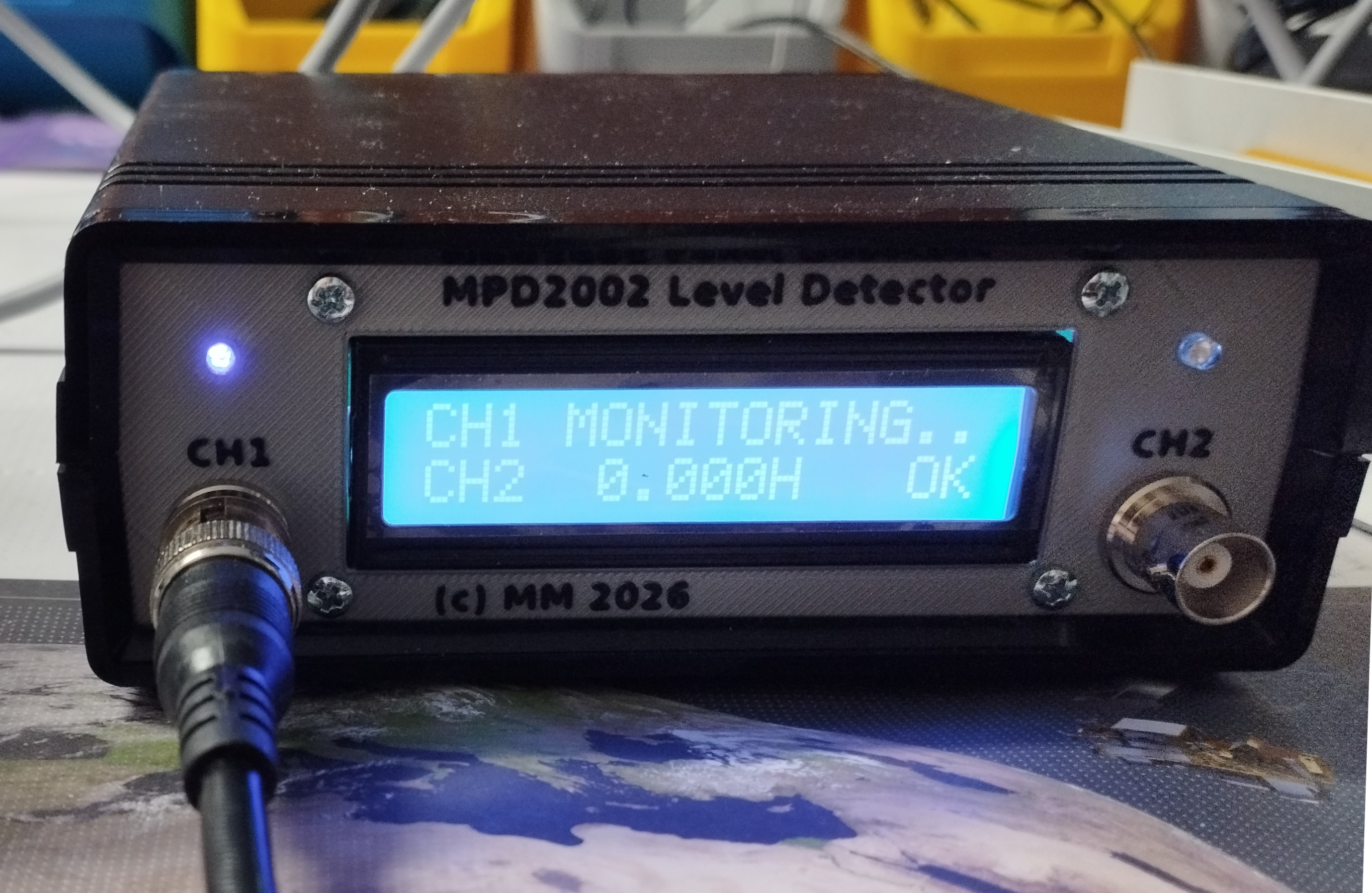
My DIY Level/Pulse Detector
My DIY Test Control Software
Linear Power Supply